
Stagnation Control
Background on Stagnation
Stagnation and its Hazards
'Stagnation', or 'stagnation conditions', occur when the solar collector cannot adequately reject the absorbed solar heat to its primary heat transfer fluid. This results in the collector and heat transfer fluid reaching temperatures far exceeding that of their designed limits. This can happen during sunny period power failures, component failures, system servicing or repair, and pump-controller intervention due to energy storage capacity limitations, etc.[1]
Overheating in solar thermal collectors during periods of stagnation is an issue faced by designers and manufacturers which can lead to enormous problems for installers and owners. The degree to which stagnation impacts collector and system performance varies by system and region, but current methods of dealing with stagnation are costly, labour intensive, and unreliable.
Stagnation issues are so prevalent and detrimental that part of the main functions of the German Solar Thermal Technology Platform (DSTTP) established in December, 2010 will be to seek better ways to control stagnation temperatures without reducing efficiency while lowering costs. [2]
A cost effective and reliable method of stagnation control in solar thermal collectors will help improve system performance, reduce maintenance costs and extend the life of both domestic and commercial solar thermal systems.

Problems in Solar Thermal Systems Attributed to Stagnation
Boiling of the Heat Transfer Fluid - Glycol-based Systems [3]:
- Degrade faster, reducing life span and adding cost
- Deposits film on pipes and components
- Becomes acidic impacting materials
- Degradation results in the fluid becoming potentially toxic
- Higher pressure putting strain on pipes and components
- Potential for leaks
- Damage to pump(s) which are normally only rated to 110°C
- Expansion tank diaphragms normally rated to 70°C
- Control valves, stop cocks, soldered joints, seals etc.
- Leakage due to high temperature liquids and steam
- Steam hammer/water hammer causing damage to piping and excess noise
- Reduced system life
- Increased costs for repair and maintenance
- Scalding danger
- Degradation of collector materials
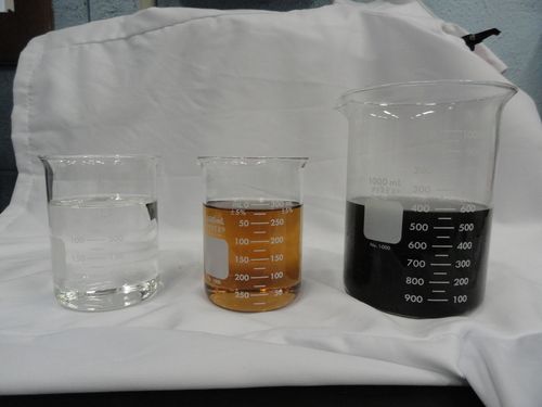
The photo above contains three states of glycol: new, clear glycol, damaged glycol and on the far right completely degraded glycol with high acidity and the formation of solids.
The Solution - Integral Stagnation Control
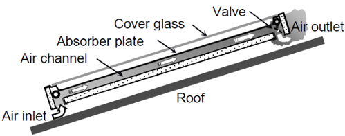
A schematic of the ISC design.
A video of our ISC technology.
Live Test Feed
Click on the button below
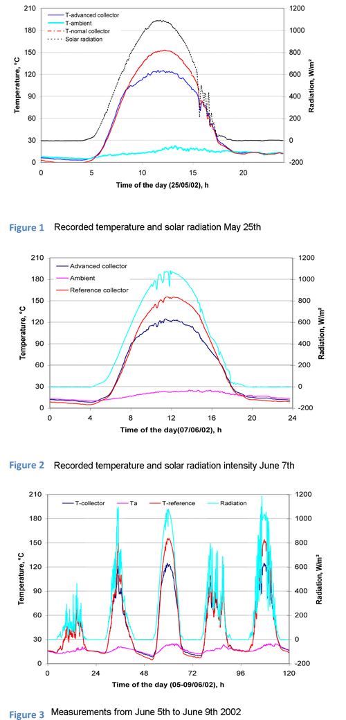
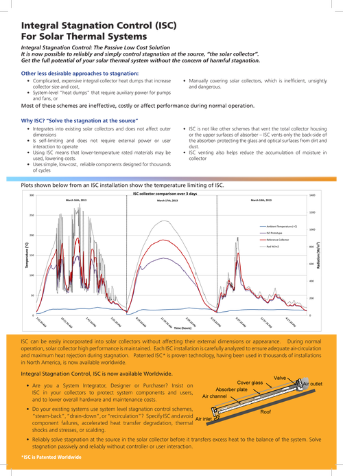
The graphs to the right illustrate the performance of the integral stagnation control valve over an extended period of time. Figures, 1 and 2 show the maximum temperatures in both collectors and the corresponding solar radiation and ambient temperatures for two clear day tests (25th of May and 7th of June).
These results demonstrate that the maximum temperature in the ISC collector was slightly higher than that in the reference collector before 100°C was reached. As the solar radiation continued to increase, the temperature of the ISC collector was observed to increase at a slower rate than the reference collector and stabilized around 122°C. The reference collector on the other hand reached a temperature of 155°C during the same period.
The results indicate that the heat loss from both collectors were effectively identical below 90°C, but above 100°C, the heat loss from the ISC collector significantly increased.
In both collectors the heat loss coefficient was calculated:
- Heat loss range for the reference collector 6.1 - 6.3 W/m²°C
- Heat loss range for the ISC collector 6.1 - 9.6 W/m²°C
Figure 3 demonstrates the 5 day period from June 5th - 9th. These figures confirm the performance of the integral stagnation temperature controls on the advanced collector and demonstrate that high temperatures in the collector absorber can be limited using this technology.
The maximum stagnation temperature of the ISC collector was determined for the case with the stagnation control disabled. This was performed to confirm the heat loss characteristics of the advanced collector without ISC and to quantify the maximum stagnation temperatures under this condition. The results obtained indicate the temperature reached by the disabled ISC collector was slightly higher than the reference collector.
With a solar radiation intensity of 1150 W/m² and an ambient temperature of 25°C, the maximum stagnation temperature was found to be 170°C in the ISC collector and 160°C in the reference collector.
It can therefore be concluded that when the stagnation temperature was above 100°C, the heat loss from the ISC collector increased and limited the stagnation temperature. The results indicated that at a solar radiation intensity of 1100W/m² and an ambient temp of 25°C a collector stagnation temperature of 120°-122°C was obtained. These results verify the operation of the ISC concept and prove that high temperatures in the collector absorber can be controlled using this technology.
Reference: Limiting Stagnation Temperatures in Flat-Plate Solar Collectors, Harrison, Lin, Mesquita; ISES 2004
Current Approaches for Controlling Stagnation
Drain Back Systems
Drain back systems are designed to allow the heat transfer fluid to drain out of the collector when there is no energy to the collector, such as during power failures or night time. Drain back system have been installed all over the world and are predominantly found in European countries.
While drain back system are effective at preventing stagnation, they have severe limitations and as a result are not ideal solar domestic hot water systems. Some of the limitations include:
While drain back system are effective at preventing stagnation, they have severe limitations and as a result are not ideal solar domestic hot water systems. Some of the limitations include:
- Labour intensive installation, requiring all pipes to be sloped appropriately allowing for proper drainage (min 10°)
- Large diameter pipes add expense
- Height restrictions limits application
- Larger pumps required to overcome static head (lift water to the highest point)
- Drain back storage tank (1 gallon per 40 sq. ft of collector) must be installed above the solar storage
Steam Back Systems
This method boils the heat transfer fluid in a closed solar collector loop, pushing the fluid into a large expansion vessel. This scheme requires precise piping layouts and collectors with good emptying properties to be effective. This emptying behaviour of the system determines the intensity, severity, and duration of the maximum temperature of the system and therefore the effects on it's components.[6]
- Installations require precise piping configurations for drainage
- Collectors must have good emptying behaviour
- Drainage issues are increased in multiple collector systems and collector banks
- Large pressure tank(s) or expansion vessels designed to withstand high temperatures
- Potential damage to components from super heated water and steam
Alternative Methods of Stagnation Control
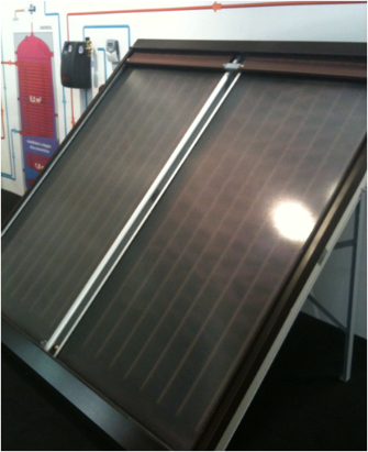
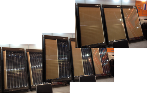
Electronic blinds role up and down and side to side in these two iterations of stagnation control at the collector. Using motors and pulley's to block the sun these systems have the potential to be costly and fail over time.
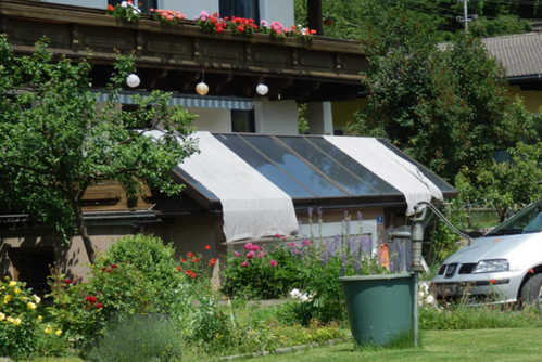
A home owner in Austria has solved his stagnation problems the old fashion way. While this method is inexpensive and simple to install on this residence most system owners are not so fortunate and this type of stagnation control is not an option.
References
1. Harrison, S.J., Lin,Q. and Mesquita, L.C.S., “Integral Stagnation Control for Solar Collectors”, 29th Annual Conference of the Solar Energy Society of Canada, Waterloo, Canada, August 2004.
2. Joachim Berner, "Generating Inexpensive Solar Heat", Sun Wind Energy Magazine, February, 2011
3. Frank Hilerns, "The Behaviour of Heat Transfer Media in Solar Active Thermal Systems in View of the Stagnation Conditions", IEA-SHC Task 26 Industry Workshop in Borlänge, Sweden, April 3, 2001.
4. Alexander Morhart, "No Standstill in the Solar Circuit", Sun Wind Energy Magazine, September, 2010